Unboxing and Assembly
- Open the Aerotenna Smart Drone Development Platform box
- Remove the airframe, and unfold the armatures; they should click into place
- Remove the four legs from the foam packing, screw them into the bottom of the frame just inside the motors
In a separate bag in the box, you should have the following equipment necessary for the remaining assembly steps:
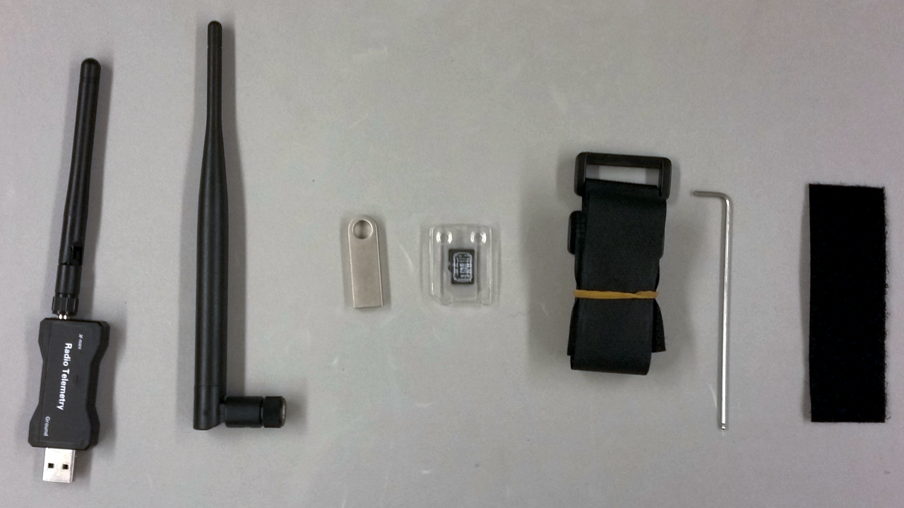
Left to right: USB Telemetry Unit; Airframe Telemetry Antenna; USB Drive with Manuals; SD Card - preloaded with flight firmware; 2 Velcro® straps; 1 Allen Wrench; 1 half of one section of self-adhesive Velcro ®
- Remove the SD card from its packaging and insert it into the OcPoC Flight Controller, there should be slight resistance and a firm click into place.
- Remove the backing on the Self-adhesive Velcro® section and firmly attach to your battery
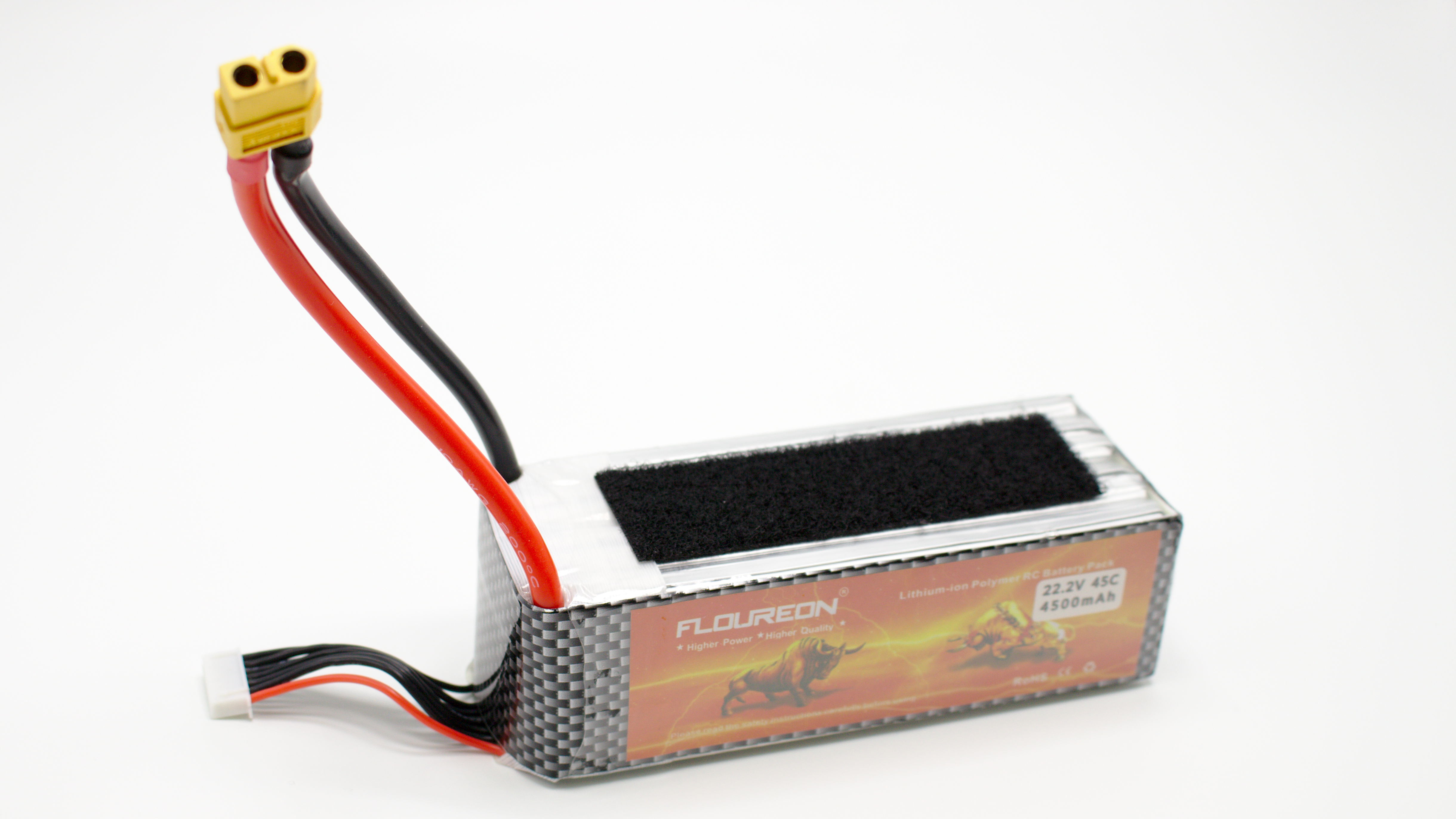
Recommended configuration for Self-adhesive Velcro
- Velcro® your battery to the underside of the airframe and securely fasten with the additional Velcro® straps.
- Ensure that all cables are connected.
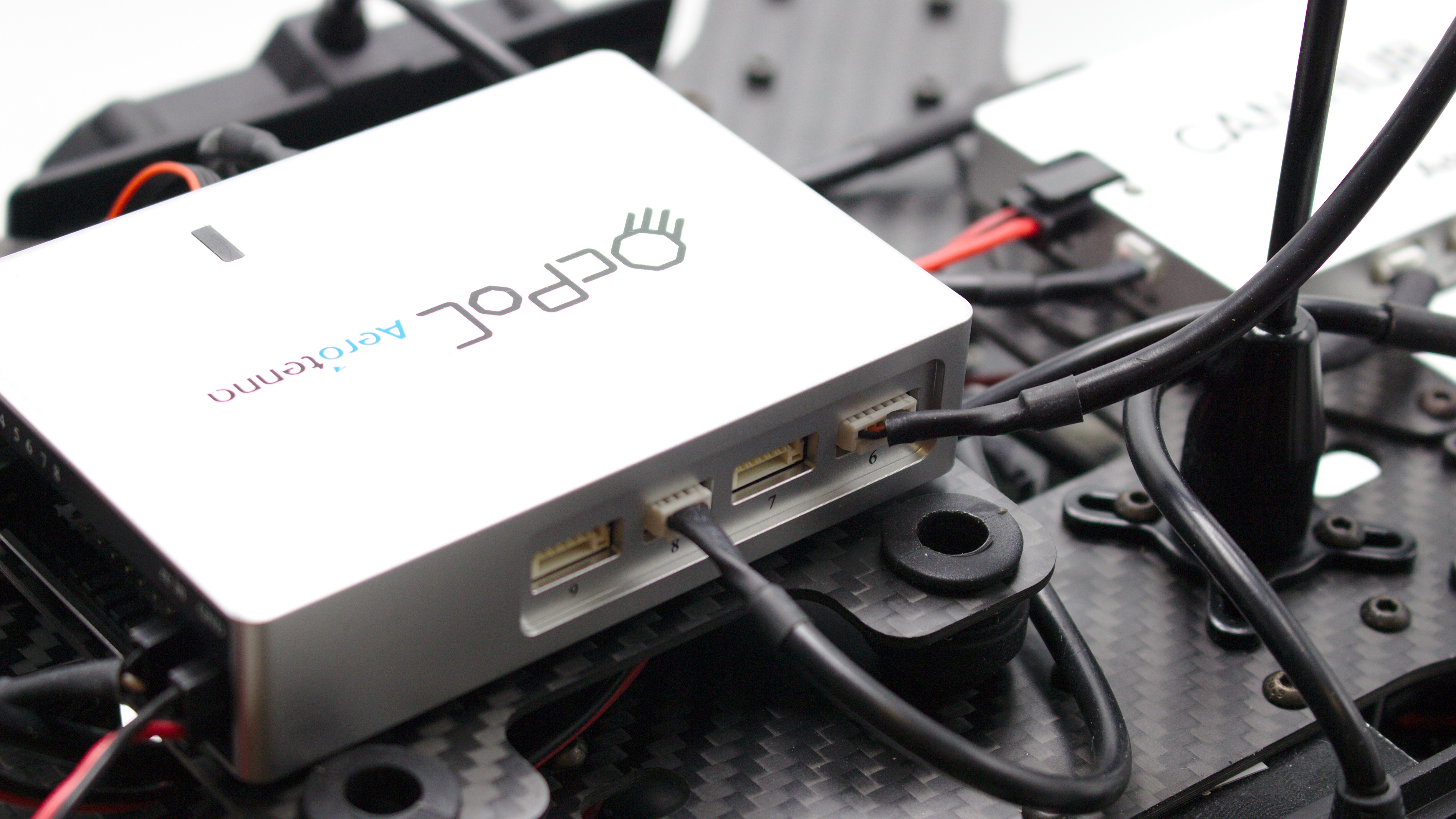
Port (Left) Side View of OcPoC Connections: Left: JST-GH 4 pin μLanding in port 8. In Ubuntu, the μLanding sends to device file /dev/ttyS6. Right: JST-GH 6 pin GPS connected to port 6. In Ubuntu, the GPS sends to /dev/ttyS3, and the built-in magnetometer sends to /dev/i2c-4.
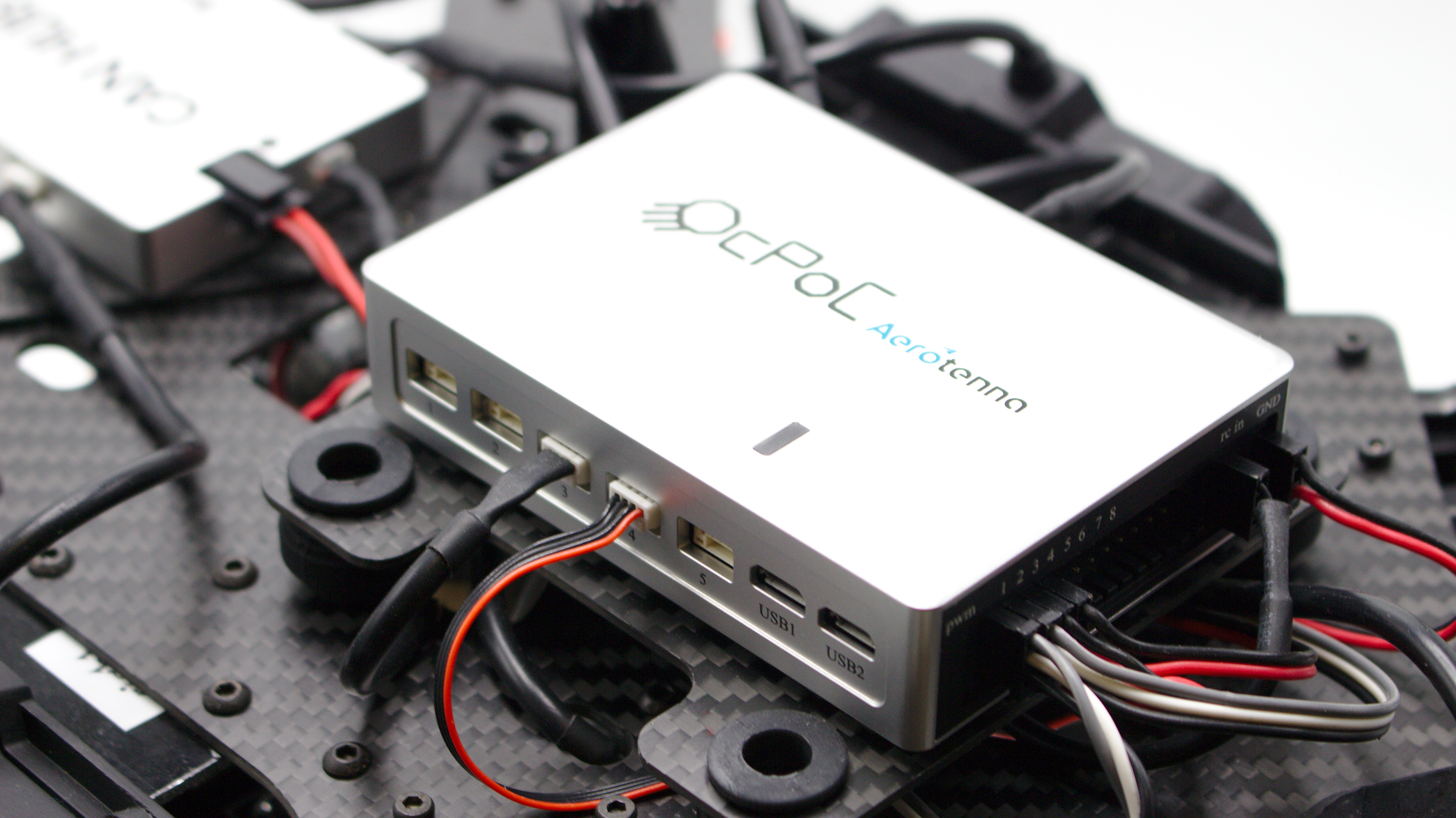
Starboard (Right) side View of OcPoC Connections: Left: JST-GH 4 pin CAN Hub in port 3. Right: JST-GH 4 pin telemetry going into port 4 - corresponds to /dev/ttyPS1
The marker on each propeller is very small, so we've included where to look for them
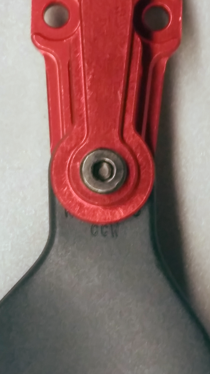
Counter clockwise indicator on a counter-clockwise oriented propeller (actual size is ~1 mm)
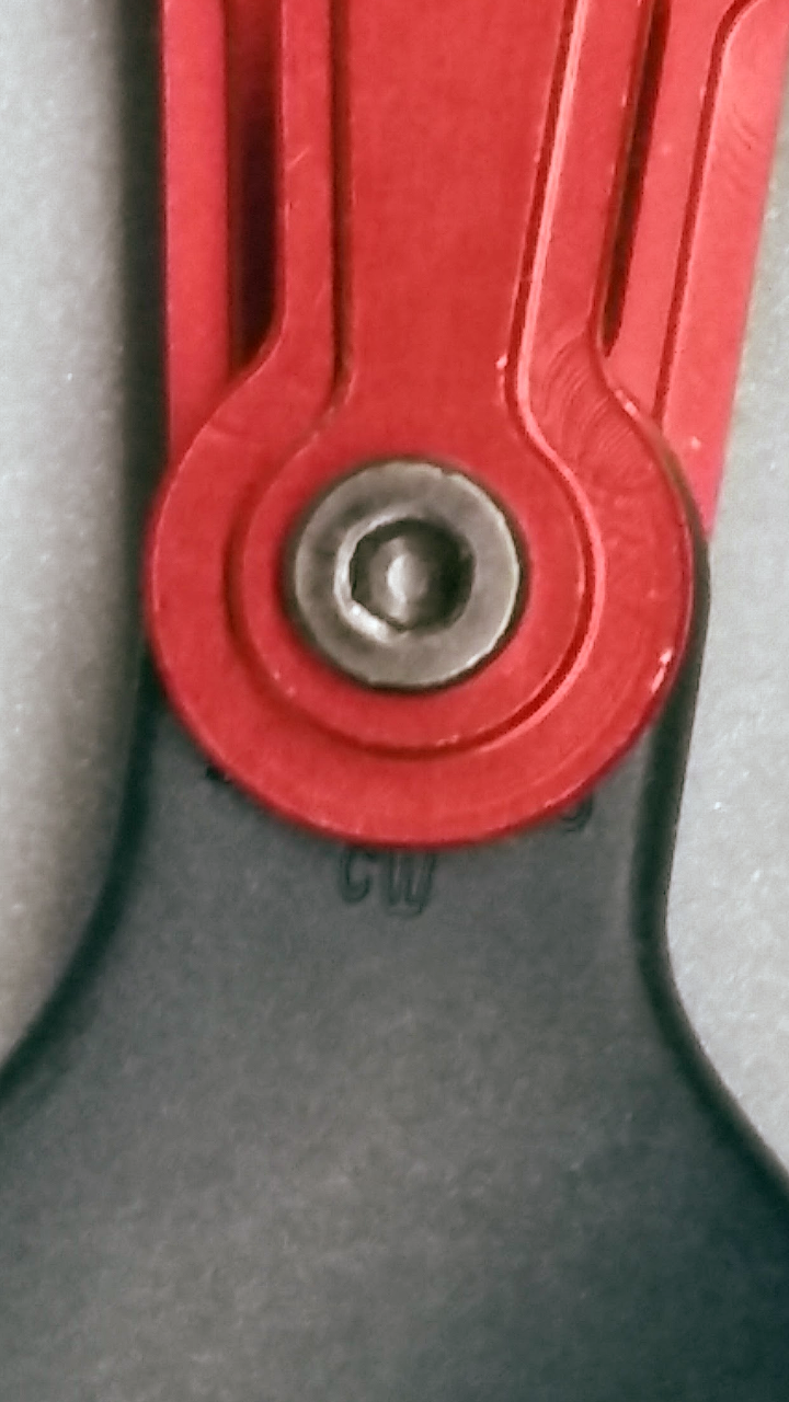
Clockwise indicator on a clockwise oriented propeller (actual size is ~1 mm)
Note:
The arrow on the GPS module points to the front of the aircraft; the rear is indicated via the ground facing μLanding.
The arrow on the GPS is subtle
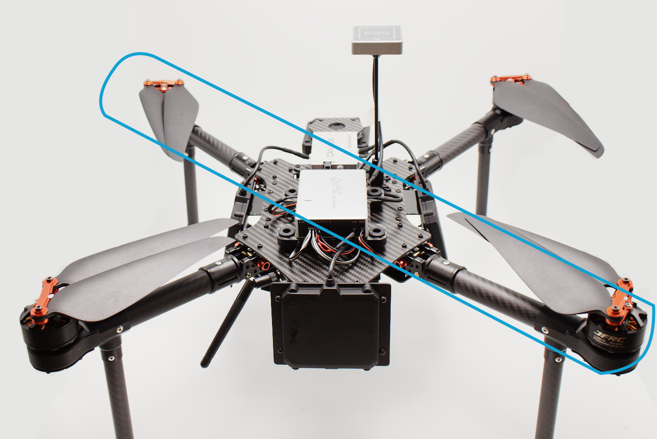
- Using the hex screws and Allen wrench provided, attach the clockwise propellers on the motors where indicated in the picture below:
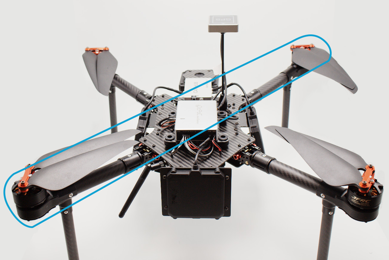
- Attach the counter-clockwise propellers where indicated in the picture below:
- Remove the foam cover concealing the controller, and unwrap the controller.
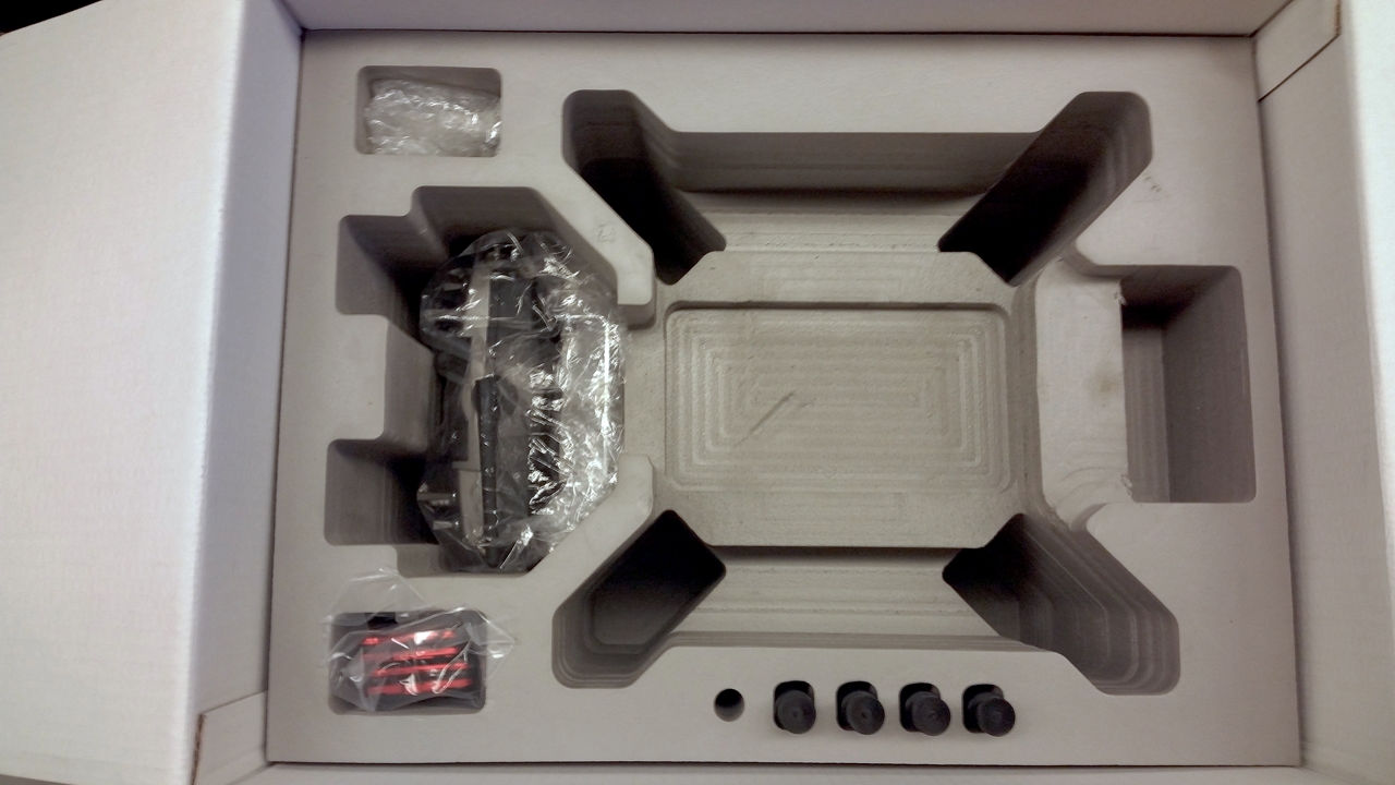
The controller is concealed underneath a section of foam under the ground detection radar (on the left in the image)
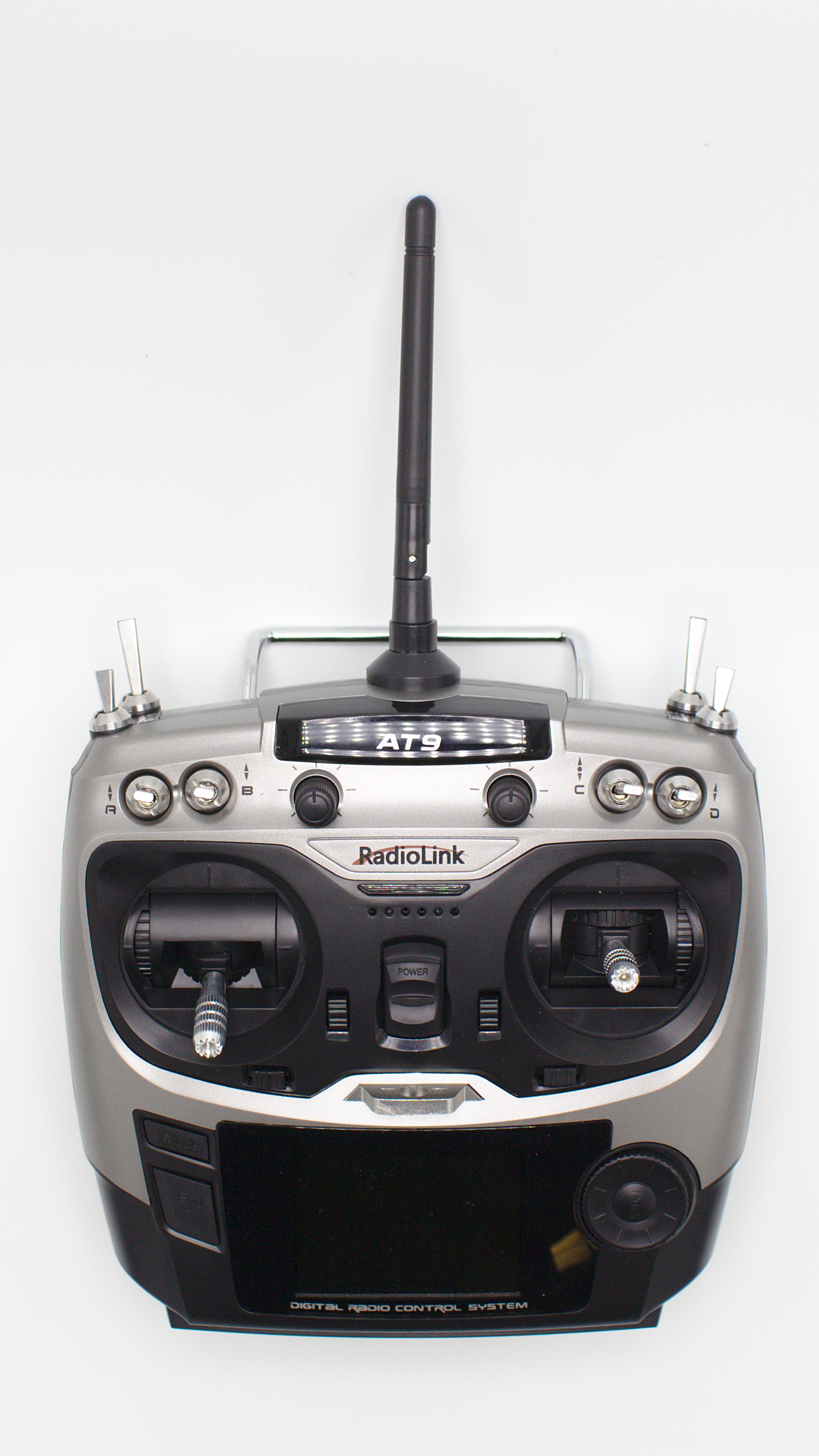
The Radiolink controller supports up to 9 channels. When shipped, the batteries are charged for storage and need to be given a full charge prior to first flight.
- Remove the battery from the controller and set it to charge
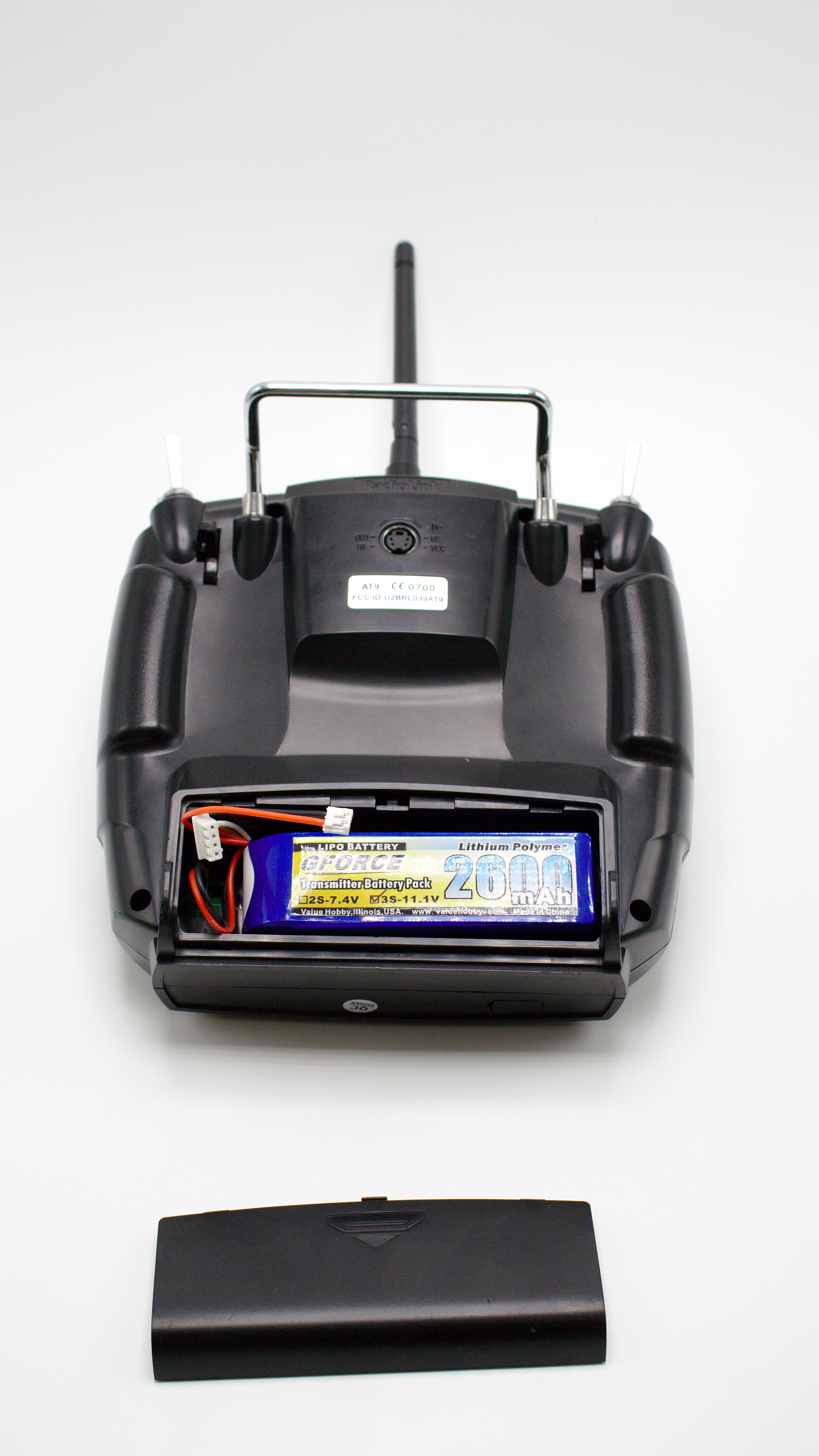
To charge the RC battery, slide open the back, disconnect the white battery clip behind the battery, and connect to your favorite LiPo charger.
ATTENTION
While the controller will turn on out-of-the-box, the battery is charged for storage and will need a full charge before flight
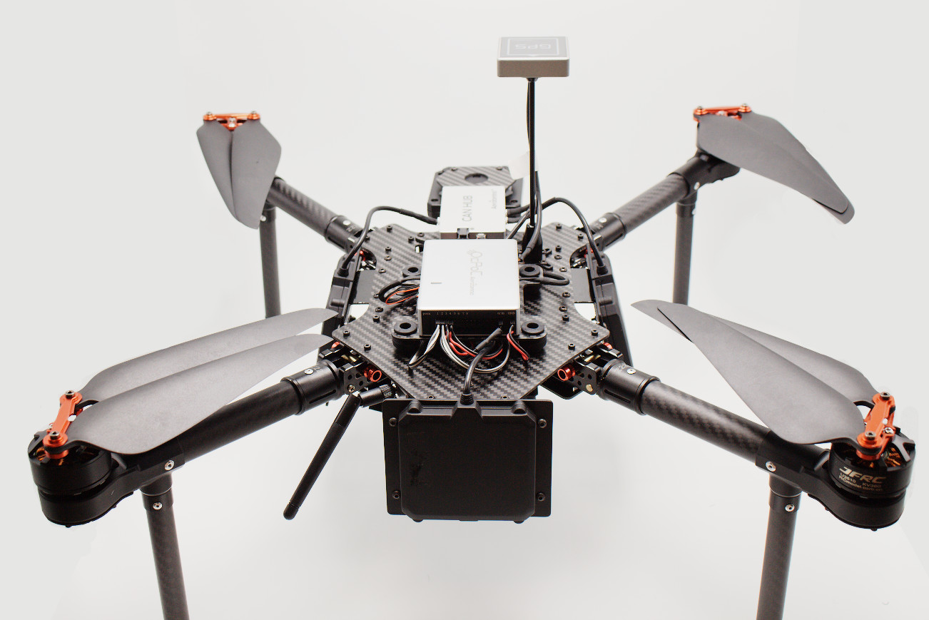
For optimal ground detection, and telemetry communication, after screwing the antenna to the telemetry unit, orient the antenna to follow the angle of the motor armature
- Connect the USB telemetry unit to a laptop or ground station.
- Once all batteries are charged, connect the drone battery to the main plug
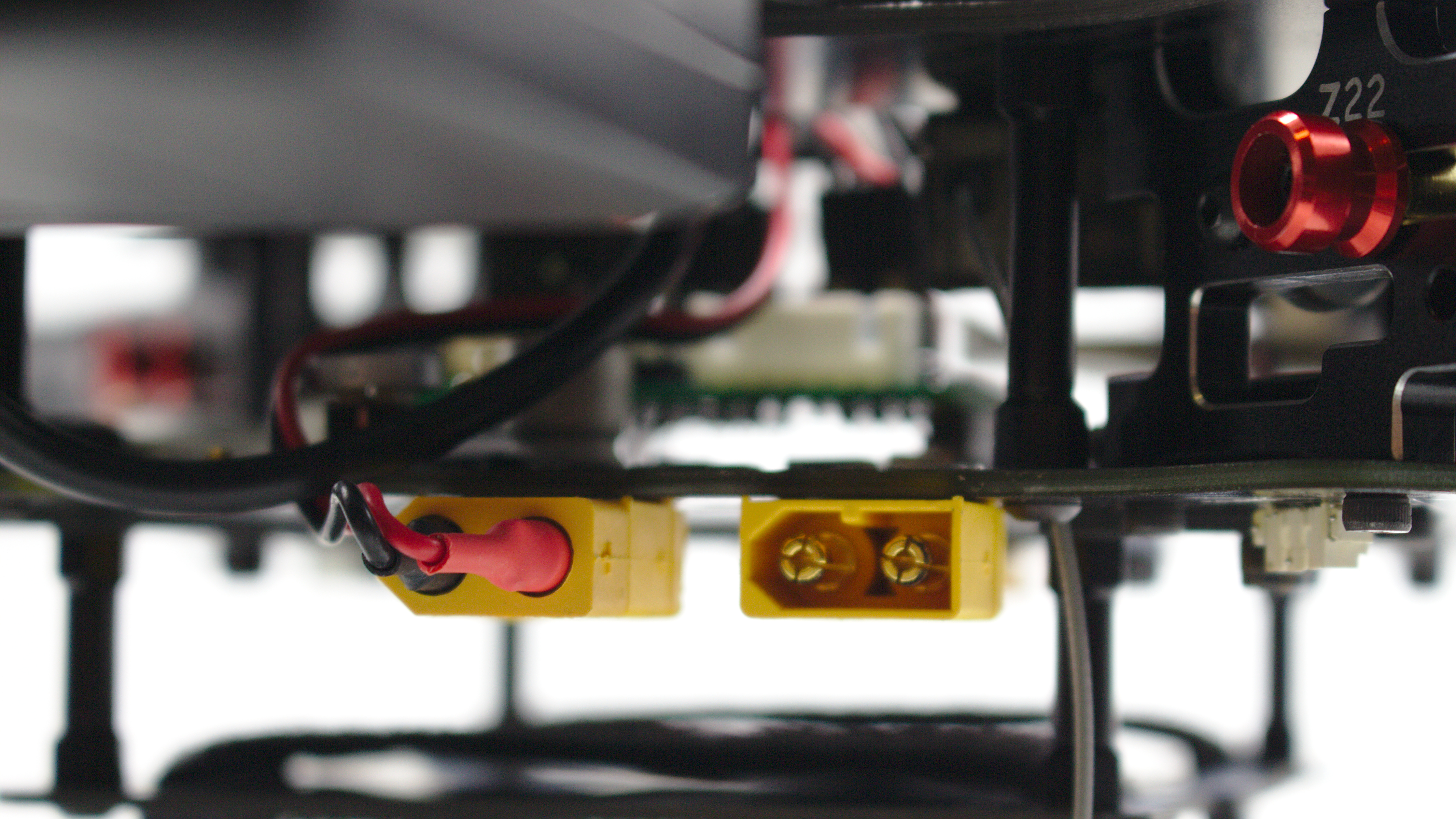
The main plug (right) supplies power to the rest of the aircraft
- Follow the instructions for your given ground control software.
Updated over 6 years ago
Be sure to check out our Built-In-Test guide for fault checks of the on board sensors. When you're ready to develop your own applications and systems, see our setup guide to further development.
